Objective
To verify the application and action of diode as a clipper; positive clipper and negative clipper and observe the waveforms
Equipment Required
Diode, Resistors, Potentiometer, DC regulated power supply, Signal generator and CRO
Theory for Diode Working as a Clipper
Diode clippers are wave-shaping circuits in that they are used to prevent signal voltages from going above or below certain levels without distorting the remaining part of the applied waveform. The clipping level may be either equal to the diodes barrier potential or made variable with a dc source voltage. Because of this limiting capability, the clipper is also called a limiter. Thus a clipper circuit can remove certain portions of an arbitrary waveform near the positive or negative peaks. Clipping may be achieved either at one level or two levels. Usually under the section of clipping, there is a change brought about in the wave shape of the signal.
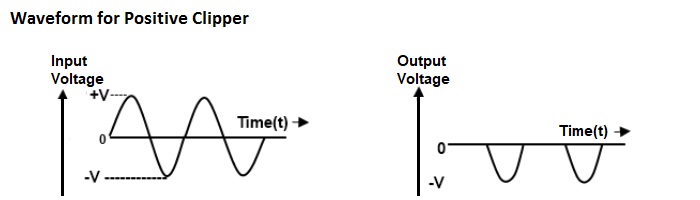
Positive Clipper
The clipper which removes the positive half cycles of the input voltage is called the positive clipper. While input side is positive, the diode D is forward biased and conducts heavily (that is, diode acts as a closed switch). So the voltage drop across the diode or across the load resistance RL is zero. Thus output voltage during the positive half cycles is zero that is; positive half cycle is clipped off. During the negative half cycles of the input signal voltage, the diode D is reverse biased and behaves as an open switch. Consequently the entire input voltage appears across the diode or across the load resistance RL if R is much smaller than RL, so the negative half cycle appears across the output.
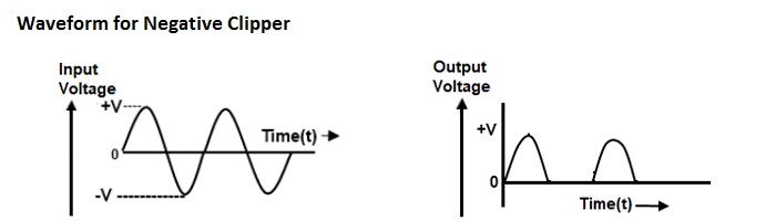
Negative Clipper
The clipper which removes the negative half cycles of the input voltage is called the negative clipper. While input side is negative, the diode D is forward biased and conducts heavily (that is, diode acts as a closed switch). So the voltage drop across the diode or across the load resistance RL is zero. Thus output voltage during the negative half cycles is zero that is; negative half cycle is clipped off. During the positive half cycles of the input signal voltage, the diode D is reverse biased and behaves as an open switch. Consequently the entire input voltage appears across the diode or across the load resistance RL if R is much smaller than RL, so the positive half cycle appears across the output.
Circuit Diagrams

Procedure
1. Before making the connections check all components using multimeter.
2. Make the connections as shown in circuit diagram.
3. Using a signal generator (Vi) apply a sine wave of 1KHz frequency and peak-to peak amplitude of 10V to the circuit.(Square wave can also be applied.)
4. Keep the CRO in dual mode, connect the input (Vi) signal to channel 1 and output waveform (Vo) to channel 2.
5. Observe the clipped output waveform. Also record the amplitude and time data from the waveforms.
6. Now keep the CRO in X-Y mode and observe the transfer characteristic waveform.
7. Vary Vref and observe the variation in clipping level. For this use variable DC power supply for Vref.
8. Change the direction of diode and repeat the procedure 1 to 7 and Vref to realize a negative clipper.
Observation
Observe the waveforms on the CRO for both the positive and negative clipper.
Result
Output voltage Vo = ...................... during positive half cycle.
Output voltage Vo = ...................... during negative half cycle.
Precautions
1) All electrical apparatus that connects to the AC power line must have a protective ground through a three-wire power cable.
2) Always double check circuit wiring before applying power. Always have a single switch or button that will immediately remove power from the circuit in case of trouble.
3) Always switch the circuit power off before changing components or connections. It is tempting to become lazy and change connections in low-power circuits with the supply on, but this is asking for trouble in the form of unintentional short circuits and blown components.
4) Always ask for directions or help if you are unsure of the correct measurement procedure or circuit connection.
Viva Questions and Answers for Diode action as a Clipper
Question.1: What is clipper?
Question.2: Explain the working of clipping circuit?
Question.3: How clipping is done using Zener Diode?
Question.4: Classify different types of clipper?
Question.5: What is the application of clipper?
Question.6: What is positive and negative clipping?
Question.7: What is oositive clipper circuit?
Question.8: What is negative clipper circuit?
Question.9: What is combination clipper?
Question.10: Give some drawbacks of series diode clippers?
Tags:
Image Credits: Freepik