To study the common food adulterants in honey, turmeric powder, Chilli powder and pepper
Objective / Aim of the Experiment
To verify the Truth Table of Logic Gates (AND, OR, NOT, NAND & NOR Gates).
Apparatus Required
All the Basic Gates or Logic Gate Trainer Kit
Theory
There are different gates available in digital electronics field which is used to perform the different tasks that are as follow:
AND GATE: - This gate is used for the multiplication of two binary digits.
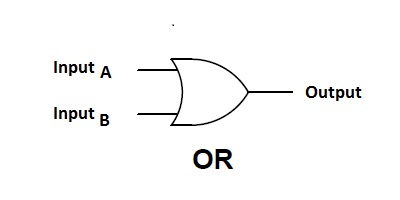
OR GATE: - This gate is used for the addition of two binary digits.
NOT GATE: - This gate gives the compliment of given binary digit.
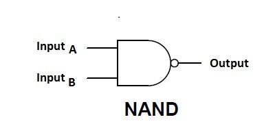
NAND GATE: - This gate is used for giving compliment of multiplication of two binary digits.
NOR GATE: - This gate is used for giving compliment of the addition of two binary digits.
Circuit Diagrams with Truth Tables
Circuit Diagram and Truth Table for AND Gate

| A | B | Output |
| 0 | 0 | 0 |
| 0 | 1 | 0 |
| 1 | 0 | 0 |
| 1 | 1 | 1 |
Circuit Diagram and Truth Table for OR Gate

| A | B | Output |
| 0 | 0 | 0 |
| 0 | 1 | 1 |
| 1 | 0 | 1 |
| 1 | 1 | 1 |
Circuit Diagram and Truth Table for NOT Gate

| A | Output |
| 0 | 1 |
| 1 | 0 |
Circuit Diagram and Truth Table for NAND Gate

| A | B | Output |
| 0 | 0 | 1 |
| 0 | 1 | 1 |
| 1 | 0 | 1 |
| 1 | 1 | 0 |
Circuit Diagram and Truth Table for NOR Gate

| A | B | Output |
| 0 | 0 | 1 |
| 0 | 1 | 0 |
| 1 | 0 | 0 |
| 1 | 1 | 0 |
Procedure
1. Place the IC on IC Trainer Kit.
2. Connect Vcc and ground to respective pins of IC trainer kit.
3. Connect the Inputs to the input swutches provided in the IC trainer kit.
4. Connect the outputs to the swtches of output LEDs.
5. Apply various combinations of inputs according to the truth table and observe the output of the LEDs.
6. Disconnect output from LEDs and note down the corrosponding multimeter voltage readings for various combinations of inputs.
Result
In this experiment we have successfully verified the truth tables of logic gate.
Precautions
- All the connection should be tight.
- It should be care that the values of the components of the circuit is does not exceed to their ratings (maximum value).
- Before the circuit connection it should be check out working condition of all the Component.
Tags:
Image Credits: Freepik


