Aim of the Experiment
To determine the thickness of a Glass Plate using Screw Gauge
Apparatus Required
Screw Gauge
Glass Plate
Theory
It is based upon the principle of a screw. It consists of a U-shaped metal frame. One end of which carries a fixed stud A whereas the other end B is attached to a cylindrical tube as shown in figure given below. A scale graduated in millimetres is marked on the cylindrical tube along its length. It is called Pitch scale.
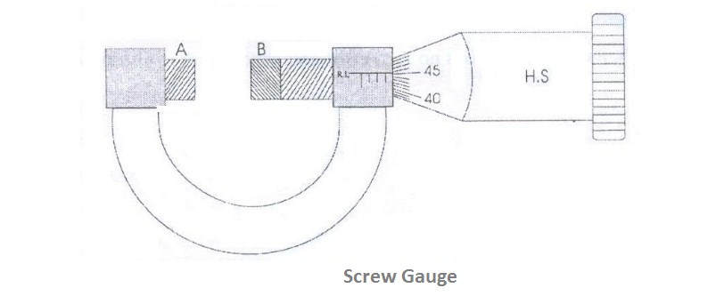
The screw carries a head H which has a beveled edge. The edge is divided into 100 equal divisions. It is called the Head scale H.S. When the head is rotated, the head scale moves on the pitch scale.
Procedure
1. To find the least count (LC) of the Screw Gauge:
Least count of a screw gauge is the distance through which the screw tip moves when the screw is rotated through one division on the head scale.
Pitch = Distance moved by the head scale on the pitch scale / Number of rotations given to the pitch scale
Least Count L.C. = Pitch / Total number of divisions on the head scale
To find the pitch, the head or the screw is given say 5 rotations and t he distance moved by the head scale on the pitch scale is noted. Then by using the above formula, the least count of the screw gauge is calculated.
Pitch = 5 mm / 5 = 1 mm
Least Count = 1 mm / 100 = 0.01 mm
The screw head is rotated until the two plane faces A and B are just in contact.
2. To find the zero correction (ZC)
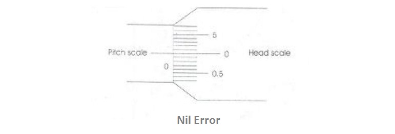
a) Nil error: If the zero of the head scale coincides with the zero of the pitch scale and also lies on the base line (B.L), the instrument has no zero error and hence there is no zero correction as shown in the figure
b) Positive zero error: If the zero of the head scale lies below the base line (B.L) of the pitch scale then the zero error is positive and zero correction is negative. The division on the head scale, which coincides with the base line of pitch scale, is noted. The division multiplied by the least count gives the value of the positive zero error. This error is to be subtracted from the observed reading i.e. the zero correction is negative as shown in the figure below:
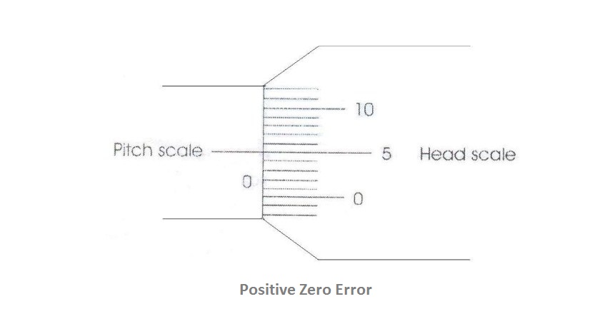
Example: If 5th division of the head scale coincides with the base line of the pitch scale then Zero error = +5 divisions
Zero correction = (Z.E x LC) = -(5 x 0.01) = - 0.05 mm.
c) Negative zero error: If the zero of head scale lies above the base line (B.L) of the pitch scale, then the zero error is negative and zero correction is positive. The division on the head scale which coincides on the base line of pitch scale is noted. This value is subtracted from the total head scale divisions. This division multiplied by the least count gives the value of the negative error. This error is to be added to the observed reading i.e. zero correction is positive as shown in the figure below:
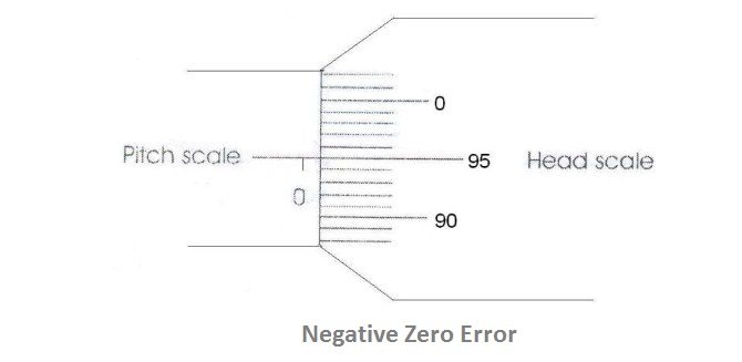
Example: If the 95th division of the head scale coincides with the base line of the pitch scale then,
Zero error = -5 divisions
Zero correction = + 0.05 mm
3. To find the thickness of the glass plate
The glass plate is gently gripped between the faces A and B. The pitch scale reading and the head scale coincidence are noted. The readings are tabulated.
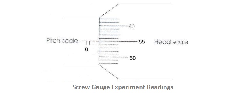
Pitch Scale Reading (P.S.R): Number of pitch scale division just in front of the head scale fully completed is noted as shown in the figure below. It is measured in millimeter.
Head Scale Coincidence (H.S.C): Coincidence of head scale division on the base line of the pitch scale is also noted.
Observation
Screw gauge readings from the above figure:
Least Count L.C = 0.01 mm
Zero error = -3 divisions
Zero correction (Z.C.) = +0.03 mm
| S.No. | P.S.R (mm) | H.S.C (div) | H.S.R = H.S.C x LC (mm) | Total Reading (T.R.) = P.S.R + H.S.R (mm) | Corrected Reading = T.R. ± Z.C. (mm) |
| 1 | 4 | 56 | 0.56 | 4.56 | 4.59 |
| 2 | |||||
| 3 | |||||
| 4 |
Result
Mean thickness of the glass plate calculated is ................
Tags:
Image Credits: Freepik