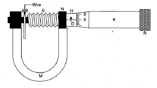
Screw Gauge is an instrument used for measuring the diametre of thin wire or similar objects or thickness of glass plate etc. Its accuracy is upto 0.001 cm or 0.01 mm and is commonly called micrometre screw gauge. It works on principle of a screw. Pitch of the screw is the distance travelled by the tip of the screw for one complete revolution the head. (or) The distance between two adjacent threads is also called the pitch of the screw. Smallest length that can be measured accurately using an instrument is called least count of that instrument.
Least count of the screw gauge = Pitch of theScrew / No.of HeadScale Division
Thickness of a plane (or) Diameter of a wire = P.S.R + H.S.R × L.C.
- If the zeroth division of the head scale does not coincide with the index line, then the screw gauge has zero error.
- If the zeroth division of the head scale is above the index line of the pitch line, the error is negative and the correction is posture.
- If the zeroth division of head scale is below the index line of the pitch line, the error is positive and the correction is negative.
Aim of the Experiment
To determine the diameter of a wire by screw gauge experiment
Apparatus Required
1. Screw gauge
2. Wire
3. Half-metre scale
4. Magnifying lens.
Theory
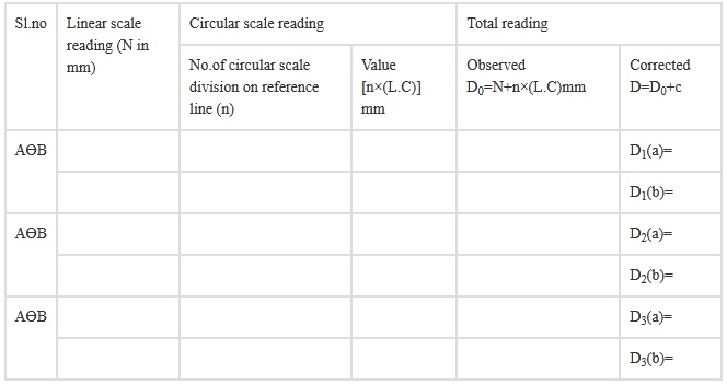
1. If with the wire between plane faces A and B, the edge of the cap lies ahead of Mb division of linear scale.
Then, linear scale reading (L.S.R.) = N.
If nth division of circular scale lies over reference line. Then, circular scale reading (C.S.R.) = n x (L.C.) (L.C. is least count of screw gauge)
Total reading (T.R.) = L.S.R. + C.S.R. = N+n x (L.C.).
2. If D be the mean diameter and l be the mean length of the wire,Volume of the wire,
V = π (D/2)2l
Procedure
1. Find the value of one linear scale division (L.S.D.).
2. Determine the pitch and the least count of the screw gauge and record it step wise.
3. Bring the plane face B in contact with plane face A and find the zero error. Do it three times and record them. If there is no zero error, then record zero error nil.
4. Move the face B away from face A. Place the wire lengthwise over face A and move the face B towards face A using the ratchet head R. Stop when R turns (slips) without moving the screw.
5. Note the number of divisions of the linear scale visible and uncovered by the edge of the cap. The reading (IV) is called linear scale reading (L.S.R.).
6. Note the number (n) of the division of the circular scale lying over reference line.
7. Repeat steps 5 and 6 after rotating the wire by 90o for measuring diameter in a perpendicular direction.
8. Repeat steps 4, 5, 6 and 7 for five different positions separated equally throughout the length of the wire. Record the observations in each set in a tabular form.
9. Find total reading and apply zero correction in each case.
10. Take mean of different values of diameter.
11. Measure the length of the wire by stretching it along a half-metre scale. Keeping one end of wire at a known mark, note the position of other end. Difference in position of the two ends of the wire gives the length of the wire. Do it three times and record them.
Observation
1. Determination of Least Count of the Screw Gauge . 1 L.S.D. = 1 mm
2. Number of full rotations given to screw = 4
Distance moved by the screw = 4 mm
Hence, pitch p = 4 mm/4 = 1 mm
Number of divisions on circular scale = 100
Hence, least count, =1 mm/100 = 0.01 mm = 0.001 cm.
3. Zero Error. (i) ........mm, (ii) ...........mm, (iii) ............mm
Mean zero error (e) = ...............mm
Mean zero correction (c) = ? e = ..............mm
Table for diameter (D)
Calculation
Length of the wire, l = (i)?..cm (ii)?..cm (iii)?..cm
Mean diameter of the wire,
D = [D1(a) + D1(b) + ............. + D3(a) + D3(b)]/6 = ............. mm = .............. cm
Mean length of the wire,
l = (l1 + l2 + l3) / 3 = ............ cm
Volume of the wire,
V = π (D/2)2l = .......... cm
Result
The volume of the given wire is ........ cm3.
Precautions
- To avoid undue pressure; the screw should always be rotated by ratchet R and not by cap K.
- The screw should move freely without friction.
- The zero correction, with proper sign should be noted very carefully and added algebraically.
- For same set of observations, the screw should be moved in the same direction to avoid back-lash error of the screw.
- At each place, the diameter of the wire should be measured in two perpendicular directions and then the mean of the two be taken.
- Readings should be taken at least for five different places equally spaced along the whole length of the wire.
- Error due to parallax should be avoided.
Sources of errors
- The screw may have friction.
- The screw gauge may have back-lash error.
- Circular scale divisions may not be of equal size.
- The wire may not be uniform.
Viva Questions and Answers for Screw Gauge Experiment
Question.1: What are the two main parts of the screw gauge?
Answer: The two main parts of screw gauge are nut and screw.
Question.2: What is the least count of the screw gauge?
Answer: The least count of the screw gauge is 0.001 cm.
Question.3: What is pitch?
Answer: Pitch is defined as the distance between two nearest threads along the axis of the screw.
Question.4: How to determine pitch?
Answer: Pitch = Main scale reading revealed on rotating circular disc / number of rorations
Question.5: When is zero-error positive?
Answer: Zero-error is said to be positive when the zero circular scale lies above the reference line only when the fixed and movable studs are in contact.
Tags:
Image Credits: Freepik